
The front-end engineering design phase—often referred to as FEED or basic engineering—plays an important role in preparing capital projects for successful execution. In addition to producing an accurate cost estimate, FEED is utilized to develop a strong scope definition, budget, and timeline while also identifying project risks. This process can be utilized for projects of all types and sizes to reduce project risk, ultimately improving risk identification, increasing budget and schedule certainty, reducing health, safety, and environmental (HSE) risks, and reducing time to achieve plant or process start-up, commissioning, and turnover.
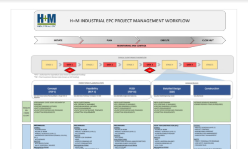
FEED is the third phase of the stage gate process (FEL 3/FEP 3) that follows a feasibility study or conceptual design. It can be done as a standalone process to enable project owners to competitively bid out detail engineering and design and construction, or it can be integrated into a formal stage gate process.
A properly executed FEED will:
- Produce engineering packages that establish a solid basis for the next phase.
- Evaluate any potential design options that may improve return on investment (ROI).
- Conduct hazardous operations reviews to improve safety outcomes.
- Support internal funding approval processes.
- Provide a robust framework or baseline that can be referenced and checked against as the project progresses through the engineering and construction phases of the project.
The FEED process gives rise to many important deliverables, typically separated by discipline, that retain value through project execution. Below, we provide information on common instrumentation and electrical FEED deliverables.
Instrumentation and Electrical FEED Deliverables List
Every capital project is unique; consequently, the depth and degree of detail for instrumentation and electrical FEED deliverables depends on project scope, owner requirements, provided items, project drivers, project characteristics, and risk. However, several common deliverables are produced during this process. A comprehensive list of common instrumentation and electrical FEED deliverables is detailed below.
- Electrical Single-Line Diagrams (SLDs): An electrical single-line diagram, also referred to as a one-line diagram, is a high-level schematic diagram that provides a visual representation of how electrical components connect and how the power flows through an electric power system in a condensed manner (i.e., a single line). A single-line diagram typically includes symbols to indicate information such as AC generators, power transformers, current transformers, circuit breakers, switches, motors, and fuses, among others.
- Instrumentation Index: An instrument index, or instrument schedule, is a document that provides a list of instrument devices used in a plant. This should include information such as tag number, type of instrument, location, service description, line or equipment number, control system, I/O type, manufacturer, model number, and reference documents.
- Major Electrical Equipment List: Major electrical equipment typically refers to large, complex equipment or longer lead items (e.g. a large transformer or motor control center). Major electrical equipment details during FEED are provided as a listing of such equipment. This list may include tag numbers, equipment manufacturers, and other information of that nature.
- Electrical Block Diagrams: An electrical block diagram is a type of electrical drawing that helps visualize principal components of a complex electrical system in the form of blocks and interconnected lines describing their relationships. This highly simplistic diagram explains the system as a whole, demonstrating the general operation and arrangement of major components. This diagram may also be used for scope splits where many third-party entities are involved or situations in which the owner may be involved and the contractor is not directly providing services and/or materials.
- Area Classification Plans: An area classification plan is a plant or facility drawing that specifies if there is a process that contains materials that are flammable or explosive in nature. This document defines the border of the flammable area so that if electrical or instrumentation equipment is installed in that area, they are rated to operate in those areas without causing a massive explosion or safety hazard. These zones are typically depicted on the drawing by bubbles of various hatch markings.
- Cause and Effects (Hazard and Operability Analysis [HAZOP]): HAZOP is a structured systematic process to identify hazards in a given work process. The work process is broken down into steps, and each step is systematically analyzed to identify any potential hazards. HAZOPs typically come from the process engineering team and are used by the electrical and instrumentation team to produce cause and effect diagrams. This diagram documents the scenarios analyzed in a HAZOP (e.g. for a shutdown case; for each process condition that causes a shutdown, a matrix will be used to depict which instruments need to be actuated or be at a certain state during a shutdown scenario).
- Motor List/Load List: A motor list, also known as a load list, is used to define process loads (major equipment in the process line powered with electricity). This listing of loads helps quantify the overall power demand on the electrical system so that equipment can be adequately sized/rated.
H+M Industrial: Planning Ahead to Keep You Ahead
Whether your capital project requires a formal stage gate process or you are looking to improve project outcomes by investing in FEED, H+M Industrial EPC has all the in-house tools, resources, and capabilities to help guide your project to the best project decisions.

The H+M Industrial Team
For over three decades, we have provided best-in-class capital project management services to Energy and Chemical industries through our proven EPC approach. We are dedicated to providing trust, experience, and efficiency through all stages of engineering, procurement, and construction--on budget and on time.

Partnering with H+M Modular
H+M Modular, a division of H+M Industrial EPC, specializes in custom fabricated equipment, modules, and skids for energy and chemical industries. The approach emphasizes the potential for decreased risk through more controlled fabrication, leading to enhanced quality and safety, reduced labor costs and construction times, improved labor availability, and solutions to geographic challenges. We are dedicated to providing trust, experience, and efficiency through all stages of traditional and modular construction projects using our proven EPFC approach, If you're considering modular fabrication, we invite you to connect with us to learn about how modular solutions can improve project outcomes.


